I have recently been thinking about building a Commodore VIC20 controlled robot. Some inspiration came from the classic 1980s Usborne How to Make Computer-Controlled Robots book [3] and the BBC Buggy[4].
You will need:
- 1 x Laser Cut it yourself tank kit
- 1 x Motor controller boar
- 1 x Commodore VIC20
- Various electronic components
- 1 x Line following board
- Microswitches
How to build:
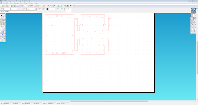
First I needed to laser cut the tank chassis. I downloaded the DXF file and opened it inTechsoft 2D Design (This is the CAD software we use with our laser cutter).
Cutting out the parts from an 5mm perspex sheet on the laser cutter
Once the parts were cut out, I set about building the tank using the tank building resource instructions.
Electronics:
Next I built the motor controller board using the supplied
instructions. The board was originally
designed to use with a 18 pin PIC microcontroller, I used a programmed PICAXE
18M2 chip[1] to test that the inputs and outputs worked correctly. The board
was functioning correctly so I set about building a suitable interface circuit.
I built a prototype circuit on a breadboard to test that I could interface
the VIC 20 user port with the FAN8100N motor driver IC on the motor control
board. I used a 74HCT244[2]. User port I/O numbers 0 to 3 are connected via
the 74HCT244 to the forward and reverse inputs on the FAN8100N motor driver IC.
These tests worked so I went on to add a simple LED display to
monitor the status of the user port and added some circuitry to interface the
inputs from the existing motor controller board with the VIC 20 user port. I then verified that the inputs worked
correctly. Now that the circuitry was working
correctly I transferred the breadboard layout onto stripboard to make things
more permanent.
I removed the existing PIC socket and soldered some Molex headers in place so I could connect the robot to my VIC20 via a 5 meter length of ribbon cable.
I removed the existing PIC socket and soldered some Molex headers in place so I could connect the robot to my VIC20 via a 5 meter length of ribbon cable.
I added some micro switches to the front of the tank and a line following board to the chassis.
 |
| Completed stripboard layout |
1 Input circuitry
Input signals from the motor controller PCB (at TTL logic 0 and 1) are applied to the inputs of the 74LS14 Schmitt trigger IC. This is an inverting Schmitt trigger, so that a logic 1 input will cause the associated output to go to logic 0. The 1KΩ resistors pull the input down to 0V (logic 0) in the absence of input signals.
A logic 0 out at the Schmitt trigger will cause the cathode of the appropriate LED in the quad opto-isolator IC to go low, so turning the LED on. This turns on the associated photo-transistor in the opto-isolator and its emitter goes high (due to the p.d across the 1.2kΩ resistors). The logic levels at these emitters are connected directly to the user port PB4-7, which are configured as inputs. The Schmitt input circuitry ensures precise triggering, whilst the use of opto-isolation obviates the possibility of damage to the microcomputer.
2 User port status LED
User port signals PB0 -7 are feed through a 74LS540 Octal buffer and line driver IC. The outputs of this IC are inverted so an logic 1 will turn the LED on in the 10 way light bar LED display.
3 Motor driver
User port signals PB0-3 are feed through a 74LS244 Octal buffers and line driver IC. The outputs of this IC are connected to the FAN8100N Motor driver IC on the existing motor controller PCB.
Mechanical assembly:
I started to assemble the chassis, once this was done I assembled the tracks.
Wiring:
Now the mechanical assembly is complete, I could start wiring things up. Each motor has a + marking on it, so I made sure the red coloured wire was soldered to that terminal.
Coding:
With all the wiring in place, I tested motors to make sure they worked correctly. I need to write some BASIC code to make the tank do something, I'll get onto that later.
 |
| Testing the sensors |
This simple program makes the robot move forward until it hits something, then reverse and swivel right or left before setting off again. I found this in the Usborne Practical Things To Do with a Microcomputer book.
10 POKE 37138,15
20 LET Y=37136
30 POKE Y,5
40 LET Z=PEEK(Y)AND16
50 IF Z<>0 THEN GOTO 70
60 GOTO 40
70 POKE Y,10
80 FOR I=1 TO 10
90 GOSUB 190
100 NEXT I
110 POKE Y,0
120 LET P=6
130 IF RND(1)>0.5 THEN LET P=9
140 POKE Y,P
150 FOR I=1 TO INT (RND(1)*20+10)
160 GOSUB 190
170 NEXT I
180 GOTO 30
190 FOR T=1 TO 100
200 NEXT T
210 RETURN
References
- A PICAXE chip is a standard Microchip PIC microcontroller that has been pre-programmed with the PICAXE bootstrap firmware code. The bootstrap code enables the PICAXE microcontroller to be re-programmed 'in position' directly from a PC.
- This is an 8-bit buffer/line driver with 3-state output. The device can be used as two 4-bit buffers or one 8-bit buffer.
- These books are now freely available as PDFs from here.
- The BBC Buggy is an small robot designed to work with the BBC Microcomputer.


